Wednesday, August 31, 2022
Sunday, February 19, 2017
Monday, February 22, 2016
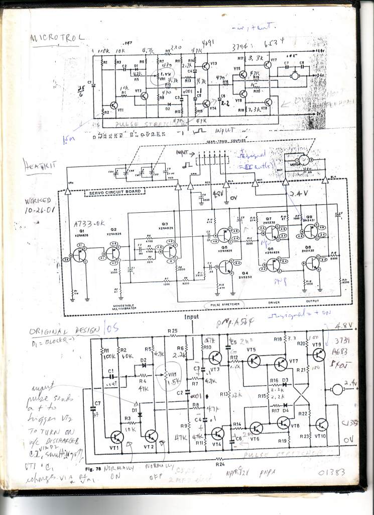
Posted here are three servo amplifier circuits popular in the 60's. Microtrol of England used the top circuit using low parts count among the circuits. It was for a power system with a center tap.(4 wire connectors). Heathkit (U.S.) also used a centr tap in the battery but is unique in using the AM radio tuner capacitor as the feedback adjuster to adjust the pulse width. The third circuit of O.S.(Japan) used a center tap as well but is the circuit that used the tap only in the final stage. As such, this circuit can be converted to a 3 wire system without a center tap in the battery system. The final stage can be converted into an H bridge circuit to run a motor rated at the supply voltage.
They all employ the same principle of producing a local pulse of the opposite polarity to the incoming pulse. Also, the local pulse is initiated when an incoming pulse appears. Two transistors wired as flip flop produces the local pulse. A POT or the tuning CAP in Heathkit's circuit controls the pulse width. When an incoming signal appears, the local pulse is initiated. since they are of opposite polarities, they cancel one another if the widths are the same. It is the differential pulse that is detected by either the PNP or the NPN transistor, depending on the polarity of the net pulse, which sends signals to the driver and final transistors to run the motor CW or CCW. The motor suns a set of gears to produce torque. The final shaft is connected to the feedback POT/CAP to adjust the local pulse to match the incoming pulse at which point no differential pulse is produced.
The author successfully duplicated all these circuits and the O.S. circuit modified to run an H bridge, eliminating the center tap.
Tke note that any of these circuits can be used as a switch to turn on a relay (horns, lights, water pump etc.) Instead of running a motor, a relay is substituted.

Wednesday, October 12, 2011

Friday, July 8, 2011
Update on RC Propo System
This update is meant for those with background in digital ICs like the shift register. itis just another perspective in explaining the RC system.
UPDATE....
THE RC SYSTEM
Early airplane modellers had one wish: to control their model aircraft remotely. Early attempts used as many as 4 strings. Then the advent of vacuum tubes promised the development of wireless control. The only thing available then in the thirties was a crystal control frequency generator which they called the transmitter and a no crystal receiver with only a relay as the output. It was soon discovered that modulating the carrier wave with a tone produced better results. The ingenious device invented was the ESCAPEMENT, the predecessor of the servo. The escapement had a rubber band providing torque to an output shaft which had a vane locked into a bellcrank . The relay pulled bellcrank which released the vane. An off center shaft then took three positions, left,center, and right. The transmitter had only one button. When pressed, it closes the relay in the receiver which unlatches the vane and allow the shaft to take a position at a time. The commands left, center, right were sequential. It was enough for the modeller at that time. In the early sixties someone had one of these in my hometown and that was the latest. The model plane was stubby, had big wings, big dihedral, and had the famous .049 COX glow engine. The plane was tossed into the air with engine at full speed. There was no throttle control. The rudder was the only control. First click veers the model left, second click center,3rd click right. 4th click center again. The next big news was the development of multi channels. Different tones were generated in the transmitter and a xylophone like reed bank sat on top of the main relay. The reeds responded to different tones. The reeds in turn activated a secondary relay which activated escapements. Later on, attempts were made to use electric motors. A crank shaft was attached to the motor shaft where a spring held the postion to center. The concept of mark space ratio was adopted to bring the motor shaft to a position by turning it on and off. The model wiggled while turning. Then geared motors were used in the fifties when PNP transistors became available. They were discovered at Bell Labs in the U.S. in 1949. To bring the final output of a motor in position, a transistor was turned on which run the motor. Then a POT adjusted the bias of the transistor till it cancels the incoming signals effect on the transistor.. This was the precursor of the modern day servo which suffered from delayed reaction to overshoot. Two Americans working in companies studying cutting edge technology used the concept of adding a locally generated opposite polarity pulse to the incoming pulse. The result was the differential pulse which could be go bothe ways by way of polarities. The pulses were repeated continously. The differential pulse was amplified which turned the motor one way or the other. A POT attached to the final output shaft of the serv and Q3o adjusted the local pulse until it matches the incoming pulse to cancel the differential pulse and thus stops the motor and maintain a new position. The system was big news and was was called PROPORTIONAL since the servo movement simulates that of a lever attached to the transmitter POT.
The standard pulse width adopted was 1MS to 2MS. The neutral position required a 1.5MS pulse. PULSE WIDTH defined the servo position. It later on became known as PULSE WIDTH MODULATION , a misnomer actually. RC radios today have 2 channels, meaning it can operate 2 servos. The pulse commands are sent to the servos sequentially. In the receiver, Flip Flop ICs are used to generate the variable width pulses sequentially to the servos similar to running lights. In running lights, the ON time for each bulb is uniform. A series of flip flops encapsulated in a package is called a shift register IC. A continous clock runs the register to light the bulbs in sequence and is usually generated by the timer IC LM555. In an RC system, after an initial clock which is cyclically generated, it is followed by subsequent clocks whose delays from the previous one can be varied. In the case of a 2 channel system, a Free Running Multivibrator called FRM cyclically generates the first clock which turns the first channel port ON. A second clock produced by a single transistor turns it OFF and the 2nd channel port ON. The third clock turns the 2nd channel port OFF. A PAUSE is introduced before the next cycle begins. Each initial pulse, and the 2 more pulses and the pause is called a FRAME. In the case of a 2 channel system, the max delays between the initial clock and the 2nd clock and on to the 3rd clock is 2MS x 2 or 4MS. If a 6MS pause is introduced, the duty cycle of the FRM is set at 10MS. When both clock delays is at 1MS, the PAUSE time becomes 8MS. The pause detected at the receiver "resets" the shift register to start with channel 1 on the next initial clock. The clock generator is called an ENCODER and the shift register is called a DECODER. The circuit below shows an ENCODER using discrete components. Q1 and Q2 form the FRM. Q2 comes on every 10MS and the small capacitor .0015 mfd discharges into diode D1 which is the initial clock. When the collector of Q2 turn negative, the timing capacitor to the base of Q3 is discharged and turns Q3 off. However, resistor to the base of Q3 recharges the timing capacitor until Q3 turns on producing the 2nd clock via D2. Same thing for Q4. However, the delays in recharging the timing capacitors can be controlled by the POTS in the collectors of Q2 and Q3. These minute clocks are amplified and made uniform to abolut .25MS by a pair of transistors in a monostable mode. The second transistor Q6, is actually a switch which shuts off evrytime there is a clock from a diode. Q6 switches off the RF section in a wireless radio system. In the receiver, the break in the carrier wave is detected and reconverted back into a clock. THUS, THE TRANSMITTER SENDS CLOCKS TO THE SHIFT REGISTER DECODER IN THE RECEIVER. The encoder and decoder can be connected by 2 wires to make a wired remote controller. The encoder can generate more clocks by adding transsistors in its chain. An 8 channel shift register is available. Therefore an 8 channel system can be constructred.
The RF sections in an existing radio can be bypassed if we desire the ENCODER to drive the DECODER via wires. That is actualy done when we use a transmitter in a flight simulator in a com puter. The crystal is unplugged and only the ENCODER is used. We may disable the RF in a receiver as well by removing the crystal. ENCODER is connected to the DECODER via a pair of wires. This is called "wired remote" which can be used for underwater craft such as a model submarine or an underwater camera.
The transmitter and receiver as well as the servo amplifier can all be made using discrete components. All parts are locally available. Even the decoder can be made using transistors. It is however practical to use a shift register IC for a decoder. ICs can also be used to construct encoders in subsequent projects.
July 6, 2011
BK 0922810680
Subscribe to:
Posts (Atom)